Centrifugal Pump Theory
-
The impeller spins
& throws water out. -like swinging a bucket
of water above your head and staying dry or throwing clay
on a potter's wheel and wearing it.
-
Low pressure is formed in the
inlet. - the lower the pressure, the higher the
pump can "suck"
-
Atmospheric pressure pushes
more water in.
It
is this simple - this is the major part of pump theory. Understand
it, and net positive suction head (NPSH) is easy.
Pumps don't suck.
In
fact, nothing sucks. Can you name something that does
?Centrifugal Pump Theory also explain the workings of
several things in our world:
-
Breathing
-
Flight
-
Wind
-
Carburetors
-
Vacuum cleaners
»»
Pump Terms
Head:
Centrifugal pump curves show 'pressure' as head, which is the
equivalent height of water with S.G. = 1. This makes
allowance for specific gravity variations in
the pressure to head
conversion to cater for higher power
requirements. Positive Displacement pumps use
pressure (ie; psi or kPa) and then multiply power requirements by
the S.G.
Static Head:
The vertical height difference from surface of water
source to center line of impeller is termed as static suction head
or suction lift ('suction lift'
can also mean total
suction head). The vertical height difference
from center line of impeller to discharge point is
termed as discharge static head. The vertical height
difference from surface of water source to
discharge point is termed as total static
head.
Total Head / Total Dynamic Head:
Total
height difference (total static head) plus friction losses
& 'demand' pressure from nozzles
etc. ie: Total Suction Head plus Total
Discharge Head = Total Dynamic Head.
NPSH:
Net
positive suction head - related to how much suction lift a pump
can achieve by creating a partial vacuum. Atmospheric
pressure then pushes liquid into pump. A
method of calculating if the pump will work
or not.
S.G.:
Specific gravity. weight of liquid in comparison to water at approx
20 deg c (SG=1(
Specific Speed:
A
number which is the function of pump flow, head, efficiency etc.
Not used in day to day pump selection,
but very useful as pumps with similar
specific speed will
have similar shaped curves, similar
efficiency / NPSH/solids handling characteristics.
Vapor Pressure:
If the
vapor pressure of a liquid is greater than the surrounding air
pressure, the liquid will boil.
Viscosity:
A
measure of a liquid's resistance to flow. ie: how thick it is. The
viscosity determines the type of pump
used, the speed it can run at,
and with gear pumps, the
internal clearances required.
Friction Loss
The
amount of pressure/head required to 'force' liquid through pipe
and fittings.
»»
Reading Centrifugal Pump Curves:
Centrifugal pump performance is represented by multiple curves
indicating either:
-
Various impeller diameters at a
constant speed.
-
Various speeds with a constant
impeller diameter.
The
curve consists of a line starting at "shut head"(zero flow on
bottom scale/maximum
head on left scale). The line continues to the
right, with head reducing and flow
increasing until the "end of curve"
is reached, (this is often outside the
recommended operating range of the pump).
Flow and head are linked, one can not be changed without varying the
other. The relationship between them
is locked until wear or blockages change the
pump characteristics.
The
pump can not develop pressure unless the system creates back
pressure (ie: Static
(vertical height), and/or friction loss)
.Therefore the performance of a pump can
not be estimated without knowing full
details of the system in which it will be
operating.
The
above pump curve sample image shows:
-
Three performance curves (various impellers or speed(
-
Curves showing power absorbed
by pump (read power at operating point)
Power absorbed by pump is read at point where power
curve crosses pump curve at operating
point.However this does not indicate motor/engine
size required. Various methods are used to determine
driver size.
-
Best efficiency point (BEP(
-
Recommended operating range
(operation outside this range reduces pump life
-
Net positive suction head
required by the pump (NPSH(
-
The circled numbers indicate
the following for bottom curve (ie:
smallest diameter impeller or slowest speed curve shown:(
-
Maximum recommended head.
-
Minimum recommended head.
-
Minimum recommended flow.
-
Maximum recommended flow.
-
The points refered to as "shut
head: and "end of curve".
Read the Pump Curve
-
Select motor or engine to suit
specific engine speed or operating range
- most cost effective method where
operating conditions will not vary
greatly.
-
Read power at end of curve-most common way that ensures adequate power at
most operating conditions.
-
Read power at operating point
plus 10%-usually only used in refinery
or other applications where there is no
variation in system characteristics.
-
By using system curves all
operating conditions can be considered-best method where filling of
long pipelines, large variations in static head, or siphon
effect exist.
»»
Centrifugal Pump Operating Range
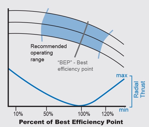
All
types of pumps have operational limitations. This is a
consideration with any pump whether it is positive
displacement or centrifugal. The single
volute centrifugal pump ( the most common
pump used worldwide) has additional limitations in operating range
which, if not considered, can drastically reduce the service life of
pump components.
Best
Efficiency Point is not only the operating point of highest
efficiency but also the point where velocity and therefore
pressure is equal around the impeller and
volute. As the operating point moves away
from the Best Efficiency Point, the velocity
changes, which changes the pressure acting on
one side of the impeller. This uneven pressure on
the impeller results in radial thrust which deflects the
shaft causing:
-
Excess load on bearings.
-
Excess deflection of
mechanical seal.
-
Uneven wear of gland
packing or shaft/sleeve.
The
resulting damage can include shortened bearing/seal life or a
damaged shaft. The radial load is greatest at shut head.
Outside
the recommended operating range damage to pump is also
sustained due to excess velocity and turbulence. The
resulting vortexes can create cavitation
damage capable of destroying the pump casing,
back plate, and impeller in a short period of operation.
When
selecting or specifying a pump, it is important not to add
safety margins or base selection on
inaccurate information. The actual system
curve may cross the pump curve outside the recommended operating
range. In extreme cases the operating point may
not allow sufficient cooling of pump,
with serious ramifications!
The best
practice is to confirm the actual operating point of the
pump during operation (using flow measurement and/or a
pressure gaug ) to allow
adjustment (throttling of discharge or
fitting of bypass line) to ensure correct
operation and long service life.
Selecting a pump
To
ensure the correct pump is selected for your application the
following details are required. If you
can not supply some of the information, just
ask for help from Rain for Rent, we can
assist in identifying your requirements.
Details required for all pumping
applications:
-
Flow rate required
-
Static suction head
-
Suction pipe inside
diameter
-
Foot valve or open pipe
-
Suction pipe length
& material
-
Static discharge head
-
Discharge pipe inside
diameter
-
Discharge pipe length
& material
-
Temperature
-
Details of solids
-
Height above sea level
-
Details of application ie:
-
additional requirements
-
sprinklers or other
pressure requirements
-
future expansion
Additional details required if liquid is not water
-
Full liquid description
-
Specific gravity
-
Viscosity
-
pH value
Data to consider for all pumping
applications:
-
Pump driver requirements
-
Electric driven -
voltage/phase/Hz
-
Electric driven - hazardous
location?
-
Diesel driven - preferences
-
Submersible pumps available
-
Class 1 Div 2 Air Operated
Diaphragm Pumps available
-
Hydraulic driven pump
systems available
»»
System Curves
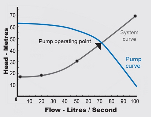
Find details of duty.In the above example: Water,
2m suction lift, 15m static discharge (17m total static
head), 360 meters of 150mm schedule 40 steel
pipe.
Draw a chart with flow on bottom scale and head on
left scale.Estimate
scale required based on size of existing pump, or guess
maximum flow expected - example shows
max flow as 100 L/S and max head as75m - sometimes you just have to
guess to get started.
Mark static head.17m at zero flow.
Note: 'Demand' pressure, ie:
sprinklers etc, should be added at each flow
point, or for approximate figures can be added to
static head.
Mark 2 or 3 other points.At 20L/S friction loss is
0.73 m / 100m of pipe, therefore 0.73 x 3.6 + 17 = 19.6
meters. Put mark at junction of 20 L/S and 19.6 m.
Repeat for other points. Remember to
add static head each time.
Join these points with a line.
You have completed the
System Curve. The Curve may have to be
extended to suit higher flow pumps.
The pump operating
point is where a pump curve crosses the system
curve. Draw as many pump curves over the system curve as you
like, to see where different
pumps will operate, or draw system curve over pump
curve.
If pump curve does not cross system curve, the
pump is not suitable.
If the pump curve crosses the system curve twice,
then the pump will be unstable and is not suitable.
»»
Pumps Operating in Series and Parallel
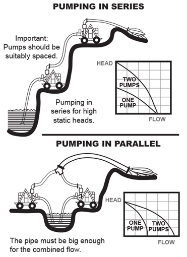
When operating pumps in parallel or in a series,
there are more complex issues to consider.
Series applications: consider the pressure rating of pump, shaft seal,
pipework and fittings. Placement is critical to
ensure both pumps are operating within
their recommended range and will have a
constant supply of water. Drawing a curve for 2 or more
pumps is simple, draw 1st pump curve then draw 2nd curve,
adding the head each
pump produces at the same flow. More curves can be added in
the same way.
Parallel applications: confirm suitability of pumps
by drawing a system curve (often 2 pumps will only deliver
slightly more than one pump due to excessive
friction loss. Also you can confirm
that pump operation will be within its recommended range.).
Non return valves are required especially if
one pump operates alone at times.Dissimilar
pumps or pumps placed at different heights requires
special investigation. Drawing a curve for 2 or more pumps is
simple, draw 1st pump curve then
draw 2nd curve, adding the flows each pump
delivers at the same head. More curves can be added in the
same way.
What
causes pump cavitation?
There are two main
causes to cavitation.
-
NPSH (r) EXCEEDS NPSH (a)
Due to low pressure
the water vaporizes (boils) and higher pressure
implodes into the vapor bubbles as
they pass through the pump causing reduced performance and
potentially major damage.
-
Suction or discharge
recirculation
The pump is
designed for a certain flow range, if there is not
enough or too much flow going through
the pump, the resulting turbulence and vortexes can
reduce performance and damage
the pump.
NPSH:
Net Positive Suction Head
Is NPSH a dirty word?
There is enough fear of it to suggest it is. But why?
Because some people will not accept that pumps don't suck.
If you accept that a
pump creates a partial vacuum and atmospheric
pressure forces water into the suction of the
pump, then you will find NPSH a simple
concept.
NPSH(a) is the Net
Positive Suction Head Available, which is calculated as follows:
NPSH(a)= p + s - v - f
Where:
'p'=
atmospheric pressure,
's'=
static suction (If liquid is below pump, it is shown as a negative
value)
'v'=
liquid vapor pressure
'f'=
friction loss
NPSH(r) is the Net Positive Suction Head Required
by the pump,
which is read from the pump performance curve. Think of
NPSH(r) as friction loss caused by the entry
to the pump suction.
NPSH(a) must exceed NPSH(r) to allow pump
operation without cavitation.
It is advisable to allow approximately
1 metre difference for most installations.
The other important fact to remember is that
water will boil at much less than 100 deg C
if the pressure acting on it is less than
it's vapor pressure, ie water at 95 deg C is
just hot water at sea
level, but at 1500m above sea level it is boiling water and vapor.
The vapor pressure of
water at 95 deg C is 84.53 kPa, there was
enough atmospheric pressure at sea level to contain the vapor, but
once the atmospheric pressure
dropped at the higher elevation, the
vapor was able to escape. This is why vapour
pressure is always considered in NPSH
calculations when temperatures exceed 30 to 40 deg
C.
Affinity
Laws of Centrifugal Pumps
If the speed or
impeller diameter of a pump change, we can calculate the resulting
performance change using affinity laws.
-
The flow changes
proportionally to speed.
Double the speed / double the flow.
-
The pressure changes by the
square of the difference.
Double the speed / multiply the pressure by 4.
-
The power changes by the
cube of the difference
Double the speed / multiply the power by 8.
Remember:These
laws apply to operating points at the same efficiency.
Variations in impeller
diameter greater than 10% are hard to predict
due to the change in relationship between the impeller and the
casing.
I know you are thinking
"what does this have to do with anything"?,
but if you can understand these 'laws' then you can make
rough estimates without having to find full
information, which might not be available
anyway.
it might go something
like this:
Boss: "Hey Joe, put
this new pulley on that pump"
Joe: "But that will
speed the pump up by about 10 % which increases
the power by a third, do you reckon the motor will handle it
?"
For rough calculations
you can adjust a duty point or performance
curve to suit a different speed. NPSH (r) is affected by speed
/ impeller diameter change
= DANGER!
Pump
Troubleshooting
Only one thing is a
better troubleshooting tool than pressure
& vacuum gauges...that is:
readings from pressure &
vacuum gauges taken prior to the problem. ie:
monitoring gauge readings will help
diagnose pump and system problems quickly, by reducing the
possible causes.
Flow measurement would
allow full diagnosis of pump performance but
is sometimes expensive and usually not
possible (Cheap versions include: V notch
weir, measuring discharge from horizontal
pipe, & timing of filling /
emptying). System curves can be used in
evaluating results.
Here is a
troubleshooting table for typical pump symptoms and possible causes.
|